
WAVE ENERGY CONVERTERS (THE WEC)
The wave device technology is relatively new but promising. For the time being there are several wave technologies (defined by EMEC) and the most common are described below.
Attenuator
It is floating device, works in parallel to the wave direction. That technology allows extracting energy even from relatively low waves. Motioned by waves device actives hydraulic system which can be used to drive generator. All generation systems and apparatus are installed inside the tube section. The attenuator may consist of two or more modules attached each other and can be located on the shallows and deep water. The higher number of modules generates more energy (Fig. 27). [30], [35]
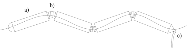
The Pelamis is one of the first constructed attenuator (capacity 0,75MW) made by PWP company. The power plant is a semi-submerged machine, consist of five modules attached each other by hinged joints. Under wave movements modules start moving relatively to another one. Installed inside the hydraulic system resists the section motions and pump the fluid to the high pressure accumulator. It allows to storage some energy (in pressure form) what assure smooth and continuous electricity generation. Produced energy is transmitting to the substation located on the shore by the lying on the seabed cable. The PWP planed to realize the next attenuator project about 10MW of capacity. The same devices, Pelamis P-750 have been installed near the Portuguese shore in number of three with total capacity 2,25MW. In the second stage of project installation of 25 more P-750 are planned. Then the total capacity of power plant achieves 21 MW. [30], [35]
Point absorbers
The point absorber is also floating machine however allow obtaining energy from all direction waves. Moreover that device is relatively small, with typical point buoy shape what allows several machines to extract energy from a single wave (depends from the wave width). The buoy extracts wave energy which can be used as a kinetic, hydraulic or pneumatic energy to drive the generator. The generating system can be housed inside the buoy or beaded to the seabed. To keep the position absorbers are attached to the floor a power take-off system, direct by the cable or by mooring. The point absorber efficiency is from 30% to 45% (Fig. 28). [30], [35]
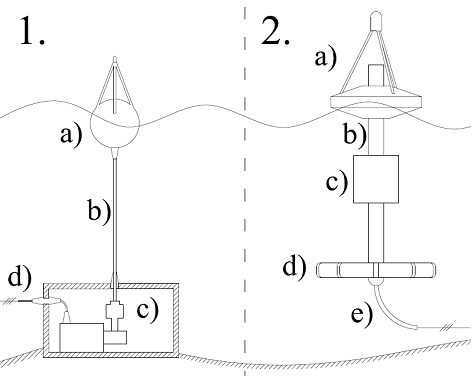
One of the first projects of point absorbers are BOLT with 45kW of capacity, and designed and constructed by Ocean Power Technologies (OPT), Powerbuoy (PB) with 150kW of capacity. The Powerbuoy consist of the buoy floating upon the water surface, power take of system, generator and control system. Generated energy is transmitting to the USP (Underwater Substation Pod) by the LV cable. At present all over the world there are several finish or under construct project: Atlantic City (New Jersey), Oahu (Hawaii), Santoña (Spain), single buoy project in Scotland, Hayle (England), Reedsport (Oregon), Coos Bay (Oregon). Those absorbers have following advantages: buoys are spaced to maximize energy capture, they have rugged, simple steel construction, utilizes conventional mooring system, simply installation (do not require special machines and infrastructure), scalable to large system (over 100MW). The PB wave energy converter generates energy for about 4400h per year.One of the first projects of point absorbers are BOLT with 45kW of capacity, and designed and constructed by Ocean Power Technologies (OPT), Powerbuoy (PB) with 150kW of capacity. The Powerbuoy consist of the buoy floating upon the water surface, power take of system, generator and control system. Generated energy is transmitting to the USP (Underwater Substation Pod) by the LV cable. At present all over the world there are several finish or under construct project: Atlantic City (New Jersey), Oahu (Hawaii), Santoña (Spain), single buoy project in Scotland, Hayle (England), Reedsport (Oregon), Coos Bay (Oregon). Those absorbers have following advantages: buoys are spaced to maximize energy capture, they have rugged, simple steel construction, utilizes conventional mooring system, simply installation (do not require special machines and infrastructure), scalable to large system (over 100MW). The PB wave energy converter generates energy for about 4400h per year. [30], [35], [36]
Oscillating wave surge converter
The WEC captures energy from wave surges and the wave movement. The device is beaded to the seabed. Therefore can be installed only in short distance from the shore and not deeper than 15 meters. Construction is relatively simply. The buoy or fan is attached to the arm, which is connected with hydraulic, pneumatic or mechanical system. The power take-off system drives the generator. The fan and buoy structure can by solid or transparent. [30], [35]
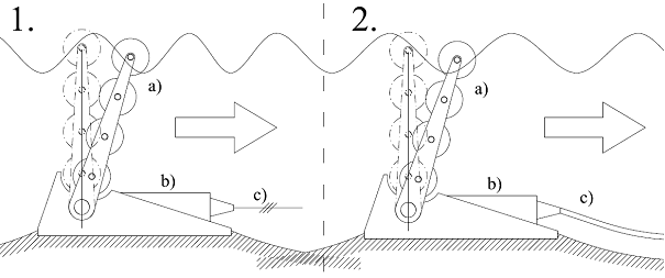
The Oyster (made by Aquamarine Power) is a near-shore wave technology with 0,8MW of capacity. When the wave motion flaps the buoy, it drives two pistons which pump the high pressure water onto the nearest shore. On the shore inside the power plant is installed turbine which converts the pressure into kinetic energy for generator. AP planned to install several Oyster devices connected to the single power plant located on the nearest coast. The Oyster wave energy converter generates energy for about 6000h per year. [30], [35], [37]
Oscillating water column
That technology uses open air cycle to drive the generator. The power plant can by installed on shore (solution with higher capacity), or on buoy (solution with lower capacity). Irregardless from method the energy is extracting in the same way. The wave action causes the water inside the column to oscillate up and down. When the wave flows into the chamber the pressure are increasing. That influence pushes the air outside the column through the air-turbine and drives them. During that exhaust the turbine extracts energy from air-movement and pass on to the generator. When the water level fall down the air are sucked back to the chamber. The symmetrical cross-section of aerofoil allows rotating the generators rotor in the same direction irregardless from the air flow direction. [30], [35]
One of the existing power plants was constructed in the Islay by the Wavegen. The capacity of existing power plants is between 20kW to 250kW. Unfortunately the on-shore technology are usable only in regions with low tidal activity because during the low tide or/and the high tide the turbine may be underwater or the air may escape by the water intake. [30], [35]
Overtopping device (the OP)
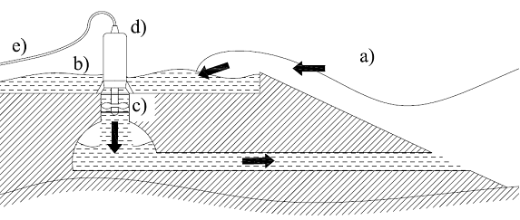
The Overtopping device can be also installed on-shore and off-shore and consist in the physical wave capturing. The captured water is storage in a reservoir with above the water surface. In the lowest point are the ducts with conventional low-head turbines. The water backs to the sea through the turbine which drives the generator. The overtopping devices have also collectors to concentrate the wave energy. Moreover there are two method of the OP devices installation: on-shore and off-shore. The on-shore power plant is the most simply system with the reservoir and generator (Fig. 31). More advanced and efficient is off-shore installation. [30], [35]
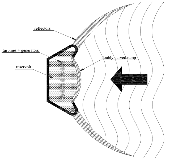
The example of the off-shore overtopping device is Wave Dragon. In March 2003 the first prototype was deployed in Nissum Bredning in Denmark. It was the first off-shore installation of the wave energy converter. The device can work alone or as a farm in climates with good wave conditions and on the depths 15 meters and above (in Nissum Bredning the experimental power plant is deployed on 6 meters depth but the next project are planed on more than 15 meters). The water collectors on the both sides of device concentrate the wave energy and focus it on the ramp. The main body has doubled curved ramp, what improves total efficiency of device. The platform are also heavy, to prevent from rolling and pitching. Due to the platform high regulation, the Wave Dragon can easy adjust to the wave activity changes. Behind the ramp is reservoir where the captured water is temporary stored. The collected water leaves through the Kaplan turbines and back to the sea (deployed in Nissum Bredining machine has 7 turbines, however larger projects with higher number of turbines are planned).Due to turbine start/stop system, the device produce high quality energy and keep smooth continuous generation. The novel mooring system is one of the main advantages of the Wave Dragon. The typical mooring system is changed for interactive flexible wires. That solution improves the amount of captured energy (Fig. 32). [30], [35]
Submerged pressure differential
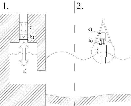
The principle of that technology are similar to the point absorbers however the buoy does not float upon the seas surface but is located underwater. That device does not extract energy directly from the wave but from the pressure differences causes by waves motion. That effect cause the buoy to move up and down what drives internal pump which create the pressure. Gained pressure can be used to generate the electricity by e.g. air turbine connected with generator by the shaft. Due to the device has to be affixed to the seabed, it may be located in short distance from the shore. [30], [35]
-
Description of technology|
Economic aspects|
Environment and public awareness|
Legislation|
Final comparison|
References