PHOTOVOLTAIC POWER SYSTEM
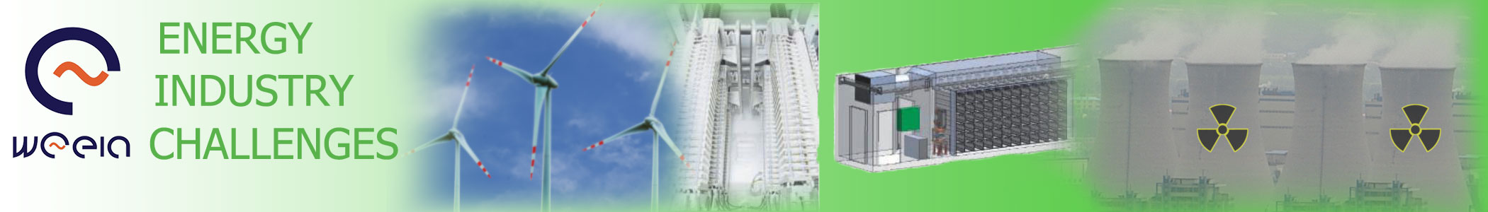
The physics of the photovoltaic (PV) cell is very similar to the classical diode with a p-n junction. The light absorption inside the semiconductor is related with electron absolve from chemical bonding between atoms. To create freed electron in semiconductor material is required to supply the amount of energy higher or equal to energy of energetic gap (1,12eV for silicon in 300K of temperature). That energy is carried by the photons. The freed electron spawns plus charge whole which can move under the influence of electric field. The charge carriers in the junction region create a potential gradient, after them get accelerated under influence of the electric field and circulate as a current in the external circuit. The power converted into electricity is equal square of the current multiplied by the resistance of the external circuit. The current flows from one material to the other until a voltage difference is established between them.[3] The primary part of PV module is PV cell. Figure bellow shows the basic cell construction (monocrystalline silicon cell-SiN).
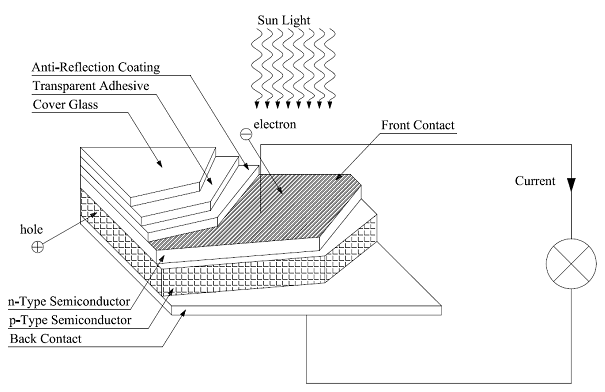
Metallic contact (Back Contact, Front Contact) on both side of the junction collects electrical current induced by the photons. A thin conduction mesh of silver fibers on the top surface (illuminated) is in charge of collecting the current and lets the light through. Special construct of the mesh consist in maximizing the electrical conductance and light penetrability. The anti-reflection coating absorbs as much light as possible by minimizing the reflection. The mechanical protection is provided by a cover glass attached with a transparent adhesive. The efficiency of monocrystalline silicon cell its around 14-18%. Although single-crystal silicon is the most widely available, the price is relatively high. That cost is related with high material cost and uneconomic production method. The most common method of producing it, consist in melting and purifying of raw silicon in a crucible. After them the seed crystal is placed in the liquid silicon and drawn at a slow constant rate. The result is a solid, single-crystal ingot, which is sliced into 200-400µm thick wafers. The wafers are later cut into rectangular cells to maximizing the number of cells which can be installed on rectangle panel. In that method more than 50% expansive material is wasted. [3], [12], [16] Much faster and cheaper are Polycrystalline and Semicrystalline silicon cells. Production method consists in casting the molten silicon into ingots and forms multiple crystals during the process. The polycrystalline cells efficiency is lower than monocrystalline (12-15%) but the costs are much lower what gives relative low cost per watt of power. The cells can be make as a thick- and thin film and is overtaking the cell market in commercial applications. [3], [12], [16] One of the latest types of PV is copper indium diselenide (CuInSe2 or CIS), cadmium telluride (CdTe) and gallium arsenide (GaAs). All of them are thin-film materials (a few micrometers or less) directly deposited on a glass, plastic, stainless steel, ceramic or other compatible substrate material. That technology uses the least material per square meter thus is inexpensive per watt of power. Moreover that cell has high efficiency from 10% even to 15% for CdTe.[3], [12], [16] One of the relatively cheap PV technology is amorphous silicon. Production consists in deposit a 2µm thick amorphous silicon vapour film on a glass or stainless steal roll. Therefore needed amount of material is very low (1% comparative with crystalline silicon). The efficiency is 6-7% but the cost is considerable lower.[3], [12], [16] To increase the cells efficiency, sunlight is concentrated many of times (10-100) the normal intensity by focusing on a small are by using low cost lenses. The total sunlight collection area remains approximately the same but such a cell requires much less number of cells and the PV material. Additional advantage that the cell is increased under concentrated light, even to 37%. The major disadvantage is that focusing optics provides to add the cost. [3], [12], [16] Above mentioned type of PV cell have many positive and negative properties but all of them have one same disadvantage. The single-junction silicon cell can convert only red and infra red light into electricity. One way to get around this limitation is to use many different cells with more than one band gap and more than one junction. This device calls multijunction or tandem cells. The layering of multiple semiconductors with a wide range of band gaps allow to converts more energy levels of light into electricity. Through that solution PV cells can achieve higher efficiency e.g.: 35% under concentrated light for GaInP/GaAs/Ge (gallium indium phosphide/gallium arsenide/germanium) triple junction cell. [3], [12], [16] The single PV cell is only the one of elements from which are construct larger devices called PV module. Usually several cells are installed in a support frames or other construction and are connect in series and parallel circuits to achieve certain voltage, such as a common 12V or 24V and to obtain certain power e.g.: 80W, 85W, 175W etc. But the power of single module is relatively low, thus for obtain more power the modules are connected together (in series or parallel circuits) to form an array (Fig. 10). [3], [12], [13], [14], [15], [16]
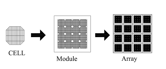
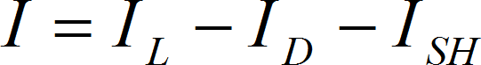
Also the arrays can be connected in series or parallel circuits to obtain certain voltage and current in case of definite power. PV modules and arrays produce direct current, thus the power inverters are required for grid connection. The equivalent electrical circuit (Fig. 11) show complexly physic of the PV cell. The current IL is generated by the module but on it way to the output it split on three other: ID the diode current, ISH the shunt-leakage current, I the output current. The shunt resistance (RSH) represent the leakage current to ground and under the Ohms Law is inversely related to ISH current. That resistance is relatively high (from 200 to 300 Ω) and do not has undue influence on modules work. Much more influence has the series resistance (RS) which represent the internal resistance to the current flow. The value depends on the pn junction depth, impurities and contact resistance. In a typical silicon cell, RS value is not higher than 0,1Ω. Nevertheless RS has significantly influence on module efficiency because even small variations can decrease the output current considerably. [3], [12], [16]
This circuit may work in following cases:
- dark current the leakage current (negligible compared to IL and ID) flows under influence of the diode-saturation current determinate by applying a voltage VOC into the no-illuminated cell. [3], [12]
- when the load current equals 0 (I=0A). Then the voltage of open circuit equals:
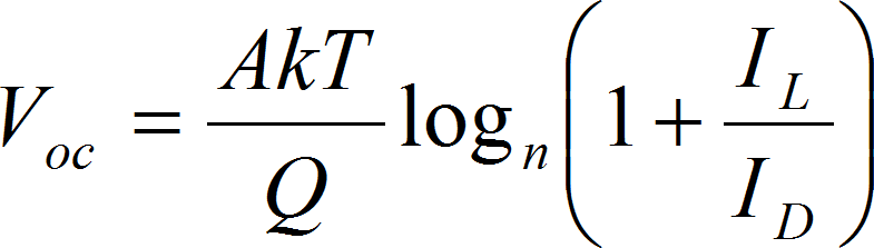
- when the cell is under full illumination and the circuit is opened, the voltage on a terminal refer describe the following expression (leakage current is negligible compared to IL or ID: [3], [12]
Even the circuit is opened for cell with nominal voltage V=1V, the theoretical voltage is equal 0,89 V in typical home temperature. This appearance is related with diffusion effect inside junction.[3], [12]
 (2.9)
(2.9) - the short-circuit current under full illumination (short-circuit current ISC): [3], [12]
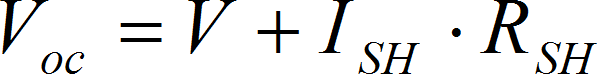
where: VOC open circuit voltage ISH the leakage current RSH the shunt resistance On the premise that the diode current as a classical diode current is given by the following expression: [3]
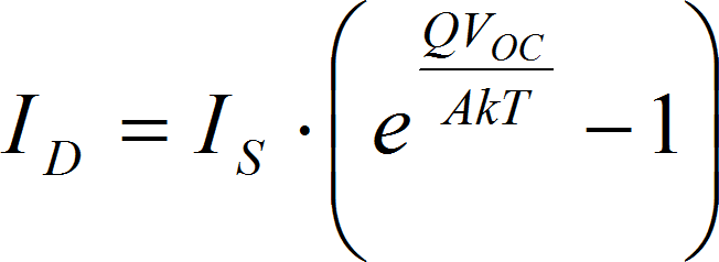
where: IS the saturation current of the diode Q electron charge (Q=1,6x10⁻¹⁹C) A curve-fitting constant k Boltzman constant (k=1,38x10⁻²³J/K) T temperature [K] Therefore the load current equals following:
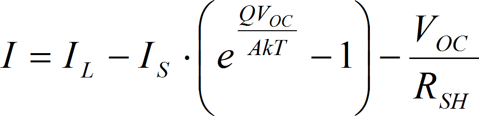
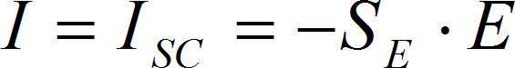
where: SE photovoltaic sensitivity E illumination intensity
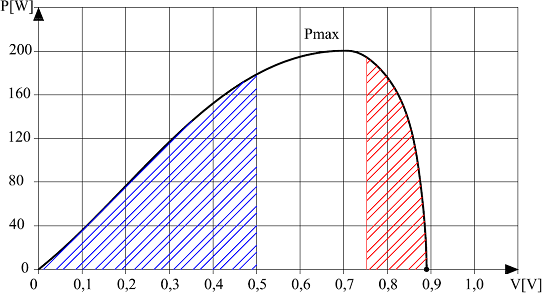
Above mentioned cases may be described on I-V (current vs. voltage Fig. 12) and P-V (power vs. voltage Fig. 13) characteristic.
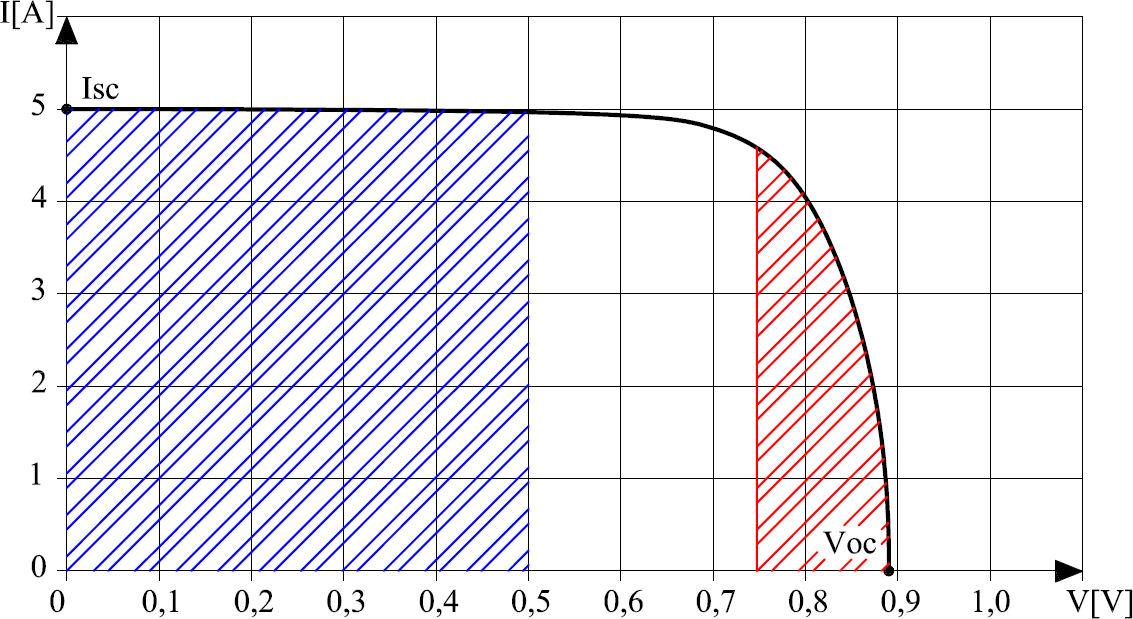
Graph shows the changes of cells current and voltage in fully illuminated conditions (illumination - 100 mW/cm2) for a typical cell (surface A=0,255cm2; efficiency - η=11,95%; fill factor FF=0,701). The left-shaded field under the curve (blue colour), it is the region when the cell works as a constant current source. The second one shaded field under the curve (red colour) it is the region when the cell works as a constant voltage source. In that case the conversion efficiency refers following expression:[3], [12], [17]
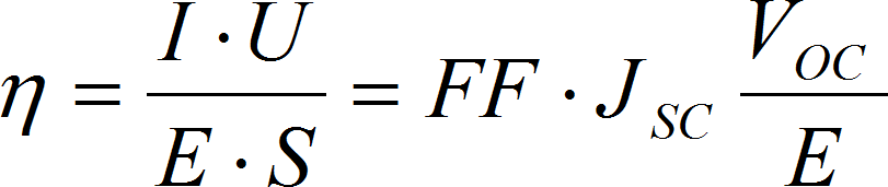
where: E illumination intensity A cells surface JSC density of short circuit current VOC open-circuit voltage
The highest value of the FF (fill factor) it is 1. That value is obtained if the current equals short-circuit current and the voltage equals open circuit voltage. But the 0,89 is FF limitation and including energy carrier recombination 0,86. It is related with diffusion effects on junction and maximal available temperature. Moreover T. Tiedje proves that the maximal value of VOC for amorphous silicon cell is around 1,1V. Assuming that the highest value of JOC = 22mA/cm2 then by the expression (2.11) the maximal value of conversion efficiency is as following :[3], [12], [19]
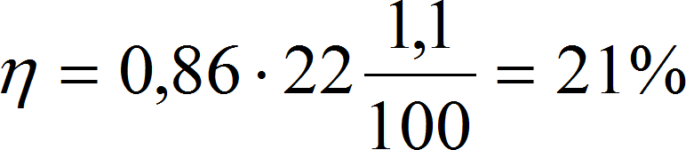
If the maximal power of the sun beams on 1m2 on the earth surface equals 1kW, thus the ideal PV module (the module dimensions 1m2) can generate 210W of electrical power. Power vs. voltage changes describes Fig. 13.[3], [12], [19]
Above mentioned efficiency 21% shows that 79% of the sun energy is lost. The losses consists of: [12]
- about 55% power stream of sun radiation is not used because photons energy are too high or too low compared with band gap of the cell material, [12]
- energetic losses related with directly and indirectly electrons recombination. The first one happens rarely and rely on that sometimes the electrons may back to the gap. Then the primary structure is redress. The second one happen more often and consist in distraction on structure defects, [12]
- the circuit resistance, [12]
- the electrode shadow on the cell surface, [12]
- the efficiency reduction cause by working in adverse temperature. [12]
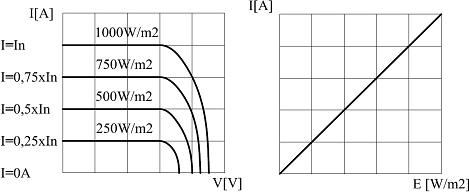
To obtain as much is possible energy from module it is important to prepare property works conditions. The major factors influencing on a module performance are: the sun intensity, the sun angle, the proper load matching, the operating temperature.[3] The sun intensity is the most variable factor. The clouded can be forecast only for few days thus the operation and regulation possibility is limited. Under a full sun the photocurrent is maximum and the value of current is in direct proportion to the sun intensity Fig.14, Fig.15. The module voltage changes slightly. [3]
The sun angle is easier to envisage. Its constantly related with latitude and season changes. Relation between photocurrent and sun incidence angle describes the following expression.[3]
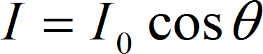
where: I generated current I0 current generated in normal condition (the sun beams angle 90°) θ the angle of the sun line measured from the normal
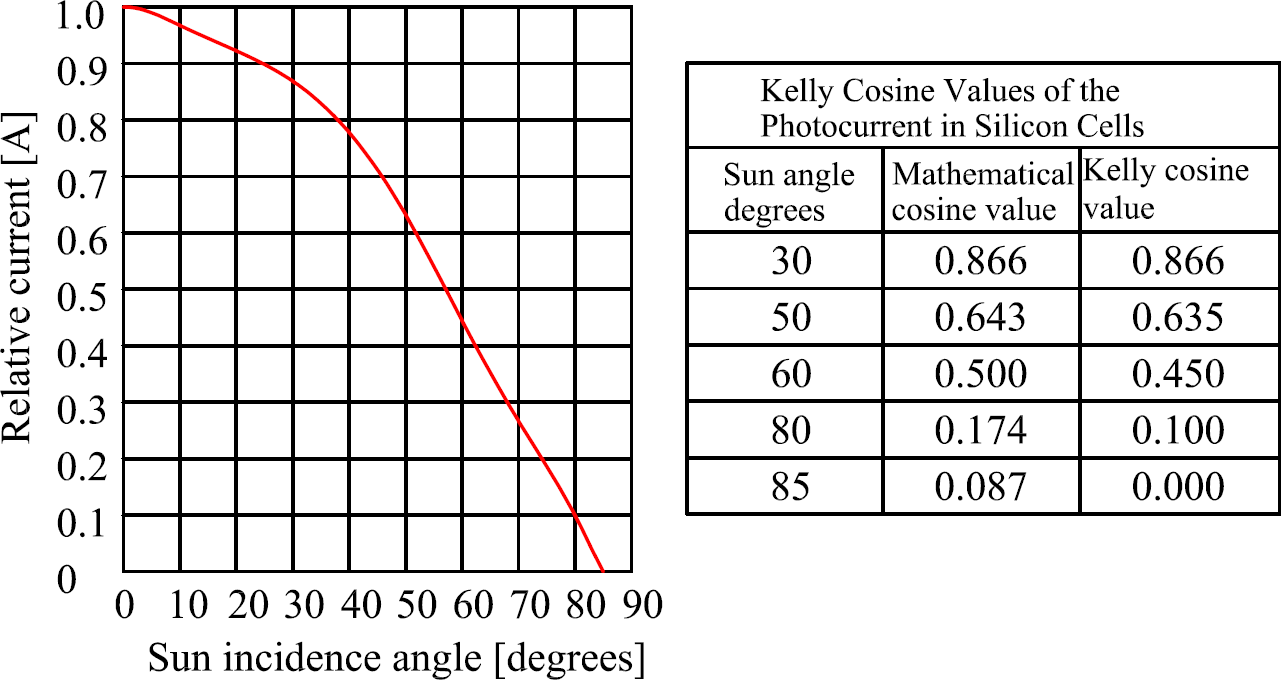
Correspondingly with mathematical cosine law even if the angle value equals 85°, the current value equals 7,5% of total current. In fact in that case the module can not generate any energy beyond 85°. Therefore for PV cells are using Kelly cosine curve, Fig.16. [3]
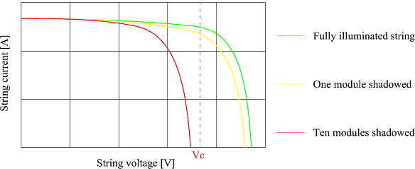
To ensure the highest value of angle (and current) very often the modules are mounted on moving structure with sun tracking system. The next operation problem, shadow effect is related with the array construction. If the large array (consist of many parallel strings of series-connected cells) get partially shadowed, one or more cells in string gets totally shadowed and loses the photovoltage. Although the current generated by the rest cells, is still flowing through shadowed cells. That cells generates no energy and becomes the load and producing losses. The operating in full sunlight cells of the same string have to work at higher voltage and cover the losses of the shadowed cell. A higher voltage in full illuminated cells is related lower current in string. The relation between shadowed area and generated current is not direct proportional (Fig. 17). [3]
If the numbers of shadowed cells are too high and the curve is below the voltage limit the generated current falls to zero. The most common method to eliminate that effect is subdividing the circuit length in several segments and bypass diodes. Then the shadowed segments do not disturb the other cells work.[3] Temperature changes also have influence on I-V characteristic. The temperature appreciation lead to increased the short-circuit current and to decreased the open-circuit voltage. Moreover the values of changes are different for both factors. That effect is described by following expressions.[3]
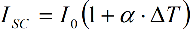
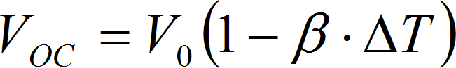
for: α≠β
Then the new power relation equals:

If the α factor is about 20 μu/°C (for a typical single-crystal silicon cell) and β factor is about 5 mu/°C (for the same cell) then the power is describe by following expression: [3]
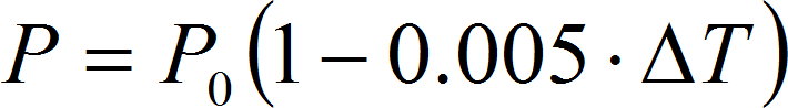
The 2.17 expression shows that 1° of temperature rise, decreased the power by about 0.5% of total value. Therefore the PV cell can generate more power (are more efficient) in low temperature. Although the voltage increase. [3] The other climate effect do not has much influence, because for a partly cloudy sky the power production is about 80% and even 30% for heavy clouds. The snow does not collect on the modules because usually the surface has plus temperature (even on frosty days) thus it melts. The mechanical endurance are enough high to withstand golf-ball-size hail. [3] Modules and arrays can be mounted in various configurations by using various construction structures. The most inexpensive mounting configuration is to lay the module directly on the roof or on the simple ground or side of pole structure. The most disadvantage of that solution is immobilizing. The module can not follow the sun and in results the module converts less energy. Therefore to improve energy conversion, modules are mounted on moveable structures like track racks structure. In this case the investment cost are higher and the mounted construction use some part of produced energy but allows to work in the best conditions longer during the day. There are two types of the sun truckers: one-axis tracker (follows the sun during the day from east to the west) and two-axis tracker (follows the sun during the day from east to the west and from north to south during the seasons). The sun tracking solution increase the energy production to 40% over the year. In the past to feed one (for one-axis tracker) or two (for two-axis tracker) motors was used a small nickel-cadmium battery but at present the tracker uses the weak light of dusk and dawn to turn the module to the east. If a dark cloud obscures the sun, the tracker aims the brightest object, till the cloud is gone. [3]
-
Description of technology|
Economic aspects|
Environment and public awareness|
Legislation|
Final comparison|
References