
CONCENTRATED SOLAR THERMAL POWER
The second one method to obtain the sun energy is concentrated solar thermal power. That method of the sun energy conversion consists in the sun light concentration on a receiver. There are three main power plant configurations with similar methods: parabolic solar collectors system, solar dish-engine system and solar power tower system. The structure of the first one type (trough solar system) consist of long rows (300-600m) of parabolic reflectors which concentrate the solar radiation on a long pipe (absorber tube) situated in reflectors focal point (Fig. 18). [20], [22]
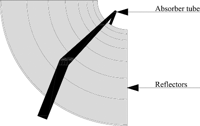
Absorbers tubes are connected with solar field piping and by them to the typical close-loop Rankine cycle. At first the working fluid (usually it is molten salt, oil or water) is heated to about 150°C, and then when flows in to the absorber tubes heated again (in this case by the sun radiation reflected by the mirrors) to 300-400°C (depends of climate conditions and latitude even to 500°C[22]). Although the steam is hot, the temperature is not high enough and usually is overheated to 500-600°C before goes to steam-turbine. The turbine is connected with synchronous generator which convert mechanical energy of turbine (before produced by turbine from warm energy) into electricity. From the turbine output the steam goes to the condenser, after to the feed pump and again back to the field piping. Sometimes the gas boiler is parallel connected to ensure the energy continuity if the clouds covers the sun. The concentrators are mounted on one-axis tracking system (follows the sun during the day from east to the west) which allow to follow the sun during the day. The biggest parabolic through collectors system is the SEGS (Solar Energy Generation System) in U.S.A. The SEGS consists of nine power plants with total nominal power of 354MW. [21], [22] The solar dish-engine system is similar to the CPS but the reflectors have dished shape and concentrate the sun radiation onto spot receiver located at the reflectors focal point (Fig.19).
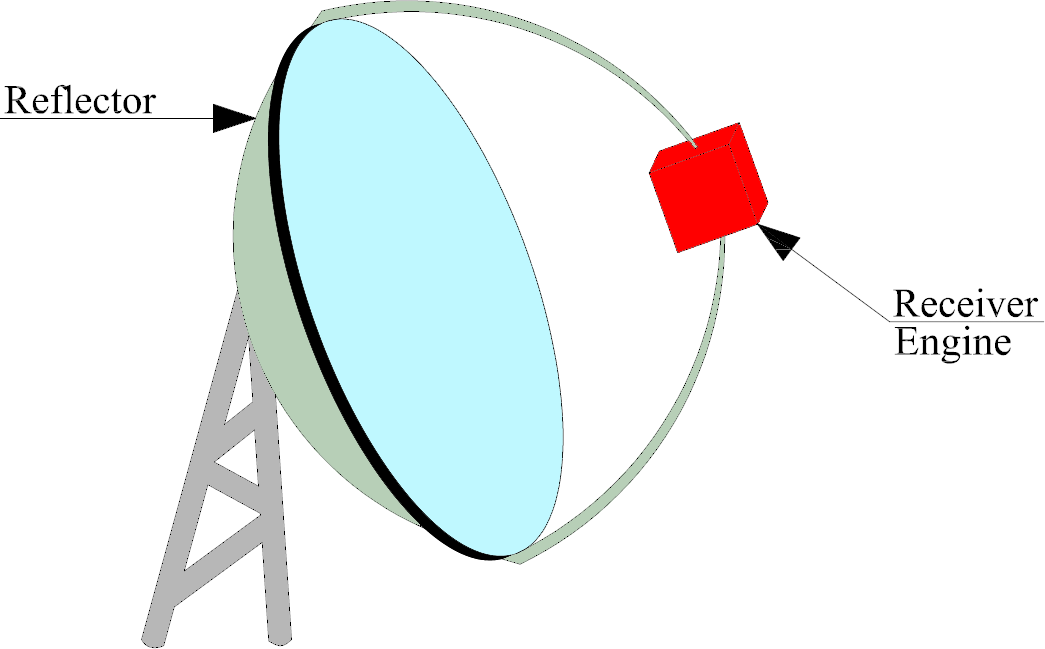
The receiver is connected with an engine which is connected with an alternator. The most common type of the engine is Stirling engine. The engine works with high temperature (700°C) and pressure (20MPa) thus the working fluid there, is helium or hydrogen. Moreover that type of engine consist of two others subtypes: direct-illumination receiver (DIR) and indirect receiver (that solution required intermediate heat-transfer fluid). When the sun radiation is reflected to the receiver where the fluid vaporizes and condensed on the engines heater tubes. There the working fluid is heated, the gas volume increase and push on a piston. After then the gas is pressed into cold cylinder where is cooling and the volume decrease. The volume decreased pulls the piston which comes back into initial position. In this way the heat energy is converted into mechanical, which is converted on electricity by installed on the same shaft alternator. The engine efficiency of total conversion (sun radiation energy into electrical energy) is about 40%, what gives the final value of total conversion efficiency about 30% (33% in hybrid mode). In use are also other types of engine e.g.: Brayton engine but the operation cost are higher and the efficiency lower, thus that solution is less common than Stirling engine. The dish-engine collectors are mounted on the two-axis sun trucker which allows following sun during the day and in every season. Typical value of power is about 25kW of electricity.[20] The last one of the most common method of the concentrated sun energy conversion consists in concentrate the reflected radiation onto the receiver situated at a top of tower. There are a few types of power plant configuration: the tower situated in a centre and the mirrors around, the tower situated between eccentrics of ellipse shaped field of mirrors or the tower located marginal of the reflectors field. The major influence on tower situation has latitude and surface configuration. Although the particular solutions are different in localization, they work in similar way (Fig. 20).
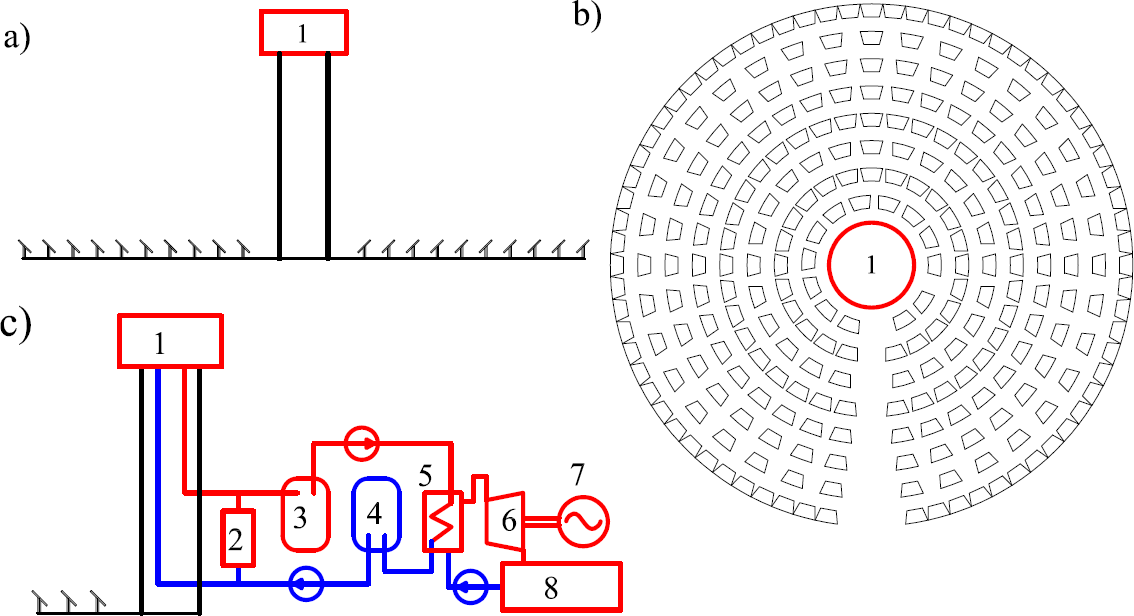
The surrounding mirrors, it usually are sun-trucking heliostats. It follows the sun, reflect radiation and concentrate them onto receiver (1), which is on of the part of Rankine cycle. In that type of power plant the liquid salt mix or water are used as a working fluid. The heated fluid (from 500°C to 1500°C) disgorges into hot salt storage tank (3). It is unusual in conventional power plant but provide continuous confluent of heated fluid into steam generator (5) when the clouds cover the sun. Obviously that solution cause energy losses but on a low level about 1%. After then the steam generator converts the fluid into steam which propel the steam turbine (6). The turbine has stiff connection with synchronous generator which generates the electrical energy in specified parameters. The uncompressed steam goes to the condenser (8) and back to the steam generator. From the steam generator, cooled fluid goes into cold salt storage tank (4) and from them again into receiver. Usual the standby boiler are connected (parallel connection) to cosset the power plant against breaks caused by long time overcast. The typical solar power tower produced about 10MW of electricity. However the USA government plans to locate in state of California solar tower power systems with total power 500MW.[21],[23]
-
Description of technology|
Economic aspects|
Environment and public awareness|
Legislation|
Final comparison|
References