
DESCRIPTION OF HYDRO TECHNOLOGY
The hydropower generation industry consists of three groups: large hydro power plant (HPP above 250MW), medium hydro power plants (between 20 and 250MW), small hydro power plat (HPP below 20MW). Generally only capacity and grid function are different however the technical solutions are similar. Depends from conditions the HPP can by construct as a flow power plant, reservoir power plant or pumped storage power plant. Generally flow power plants are construct in lowland regions due to low and inefficient water level in reservoir. Usually there are no reservoirs or it is relatively small. The power plants can stand alone, in group of several and comprise on a generation system. Those systems are called also river cascade. The cascade structures improve an energy management and allow to control water level of river during a flood states. Due to reservoir cascade system the demand peak balance is possible. In upland regions where a reservoir capacity is large enough a reservoir power plants are constructed. That method allow to easier management of water supplies. The pumped storage power plant is the last one technology. That structure consists of two reservoirs on different height above sea level. It can be man-made or natural e.g. two lakes. It is propitious if the upper water tank is supply by small water source (e.g. stream or small river) to cover vaporise and filtrate loses. The essential function of this technology is to cover energy demands during the day and storage energy overproduction during the night. Structures with larger reservoirs may storage water supplies for season or even for a few years. Average efficiency of all types of hydro power plants fluctuates between 0,7 and 0,77. [9], [10], [27]
Barrage
The major and the most expansive part of hydro power plant is barrage. It constructs across the river for water accumulation. Inside the damn are made ducts where the hydro-turbines are installed. A fine filter is installed in penstock intake to separate solid wastes from water which flow to the turbine (Fig. 36). [9], [10], [27]
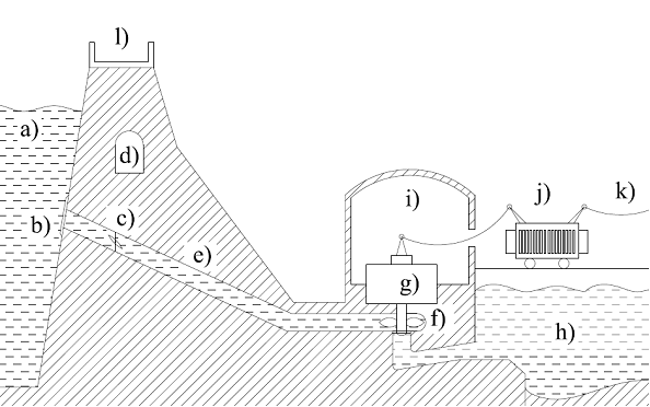
The dam is a severe problem for many species of river animal e.g.: for trout. To help them in their travel to the upper reaches the dam often has a special fish duct which allows them to pass the dam. That solution decrease the dam impact on environment however provides also to decrease the dam efficiency and adjustability easiness. Therefore on a smaller and less important rivers dams does not has fish ducts and the fishes are transported to upper reaches in unnatural way. Inside ducts are shutting to control the water flow. Above figure shows damn with butterfly shutting however there are many types depends from requirement. The next and essential device inside the duct is hydro-turbine (accurate description in next paragraph). The turbine is connected with low-head generator by the shaft (accurate description of generator in laid down paragraph). Water which flow through the turbine flows back into the river but in other side of the barrage to the lower reservoir. [10], [44]
Hydro turbines
Depends from conditions, gullet and rotor structure there are several types of hydro turbines:
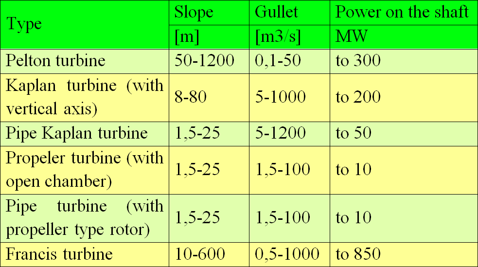
Only the Pelton turbine is active turbine (converts a potential energy into kinetic energy). The rest of them are reactive turbines (due to special inflow chamber with spiral shape the part of potential energy is converted before the water flow into turbine). [10]
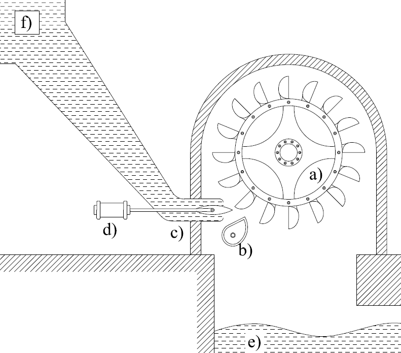
- Pelton turbine
The Pelton turbine consists of the wheel with attached double bowl vane. From the spike nozzle the water flows against the vane and gives them their energy. The used water falls down into lower reservoir. Whole rotor is above the water level of lower tank thus the vane does not touch the used water. The nozzle allows to regulate the stream. If the turbine is rapidly unburden the nozzle regulation system push water in other direction (not onto vane) and after that the sting closes the nozzle. That mechanism prevents the duct from rapid pressure elevation. The Pelton turbine required relatively high slope (Fig. 38). [10]
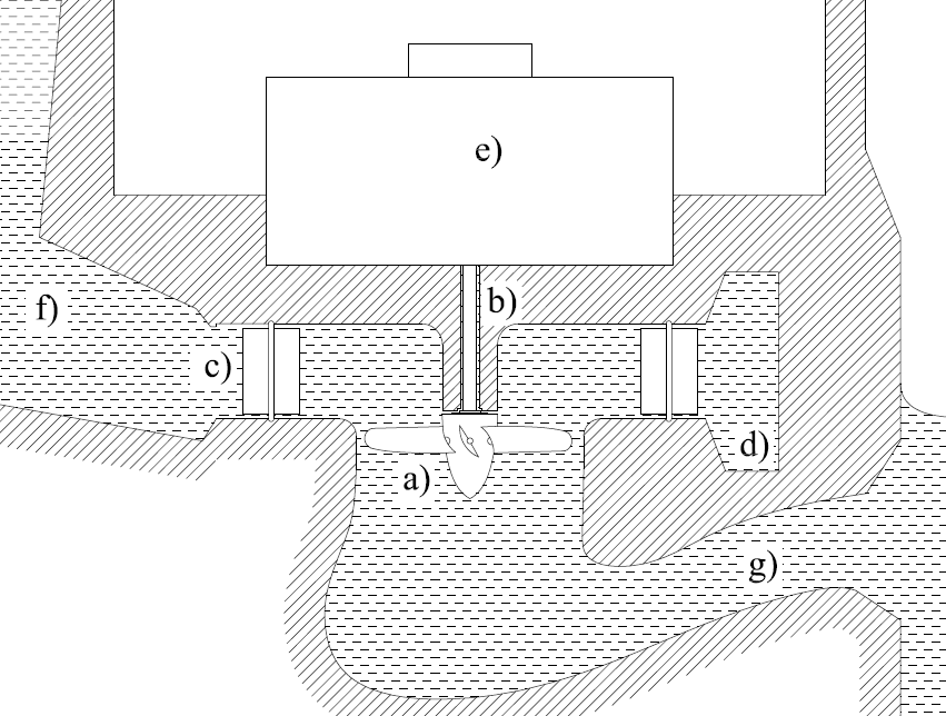
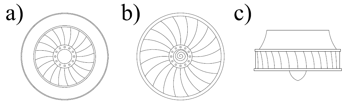
- Kaplan turbine
Structure of the Kaplan turbine is similar to screw propeller however has possibility to rotate vans. Therefore a bit alter of the Kaplan turbine is Propeller turbine. The vans drive is housed inside the rotor hub. From the duct water flow into spiral chamber where the steering system increase water velocity and provide it onto turbine vanes on whole turbine ambit. A special shape of outflow duct, the water velocity is lower in close distance of the turbine outflow than in further part of duct. Therefore a slope is a little bit increase. To improve total efficiency the vane and steering system regulation are conjugate (Fig. 39).
There are a lot of subtype of the Kaplan turbine e.g.: Bulb hydro-unit, well hydro-unit with vertical (the TAT) or skew position (the PIT), hydro-unit with external generators, Straflo type hydro-unit. [10] The Straflo type turbine has interesting and characteristic structure. The rotor circuits are installed on external ambit thus the rotor size is no limited. That solution improves moment of inertia (Fig. 40). [10]
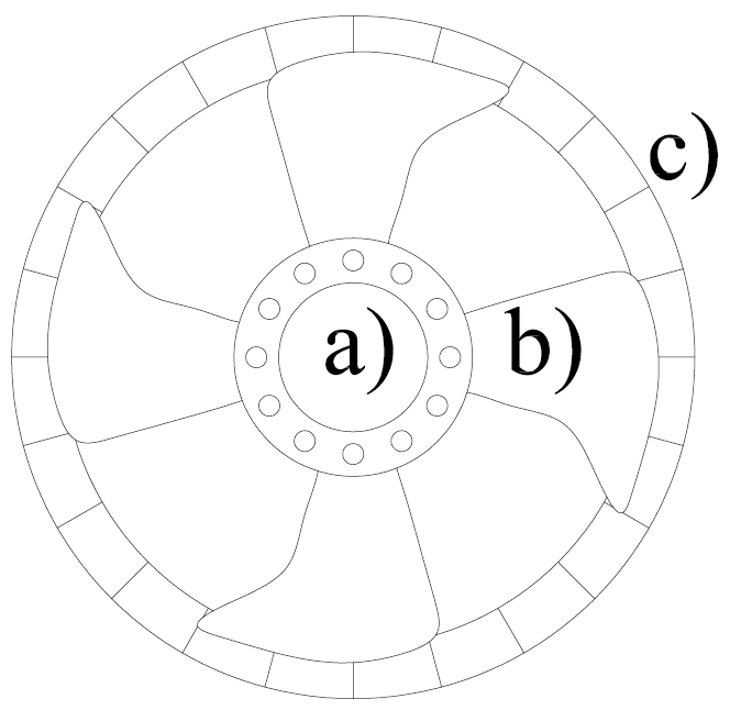
- Francis turbine
The Francis turbine consists of two coping and immobilized vane between them. The vane structure creates small ducts with uneven gauge in water flow direction. Similar to Kaplan solution, spiral chamber and steering system are housed before the turbine thus the water flows into the turbine in radial direction (Fig. 41). The reverse turbine structure based on the Francis turbine. That solution allows to operate as a turbine or as a pump, depend from case thus they are installed in pumped storage power plants. Their construction is similar to the Francis turbine however the vanes are a little bit longer. Technical parameters are also similar but the reverse turbine has about 1,5% lower efficiency. [10]
Pump mode is one of the most important advantage of the Francis turbine. The next one is relatively high power on the shaft. [10]
- Banka turbine
The Banka turbine is the less expansive and the smallest machine. Their capacity is from tens to several hundred kW thus it is solution for small power plants. This turbine can operate with relatively low slope as a small power plant. [10]
That energy extraction require pipe on inflow, outflow and steering vane. One of the disadvantages is that the turbine has to be installed above the water level in lower reservoir. [10]
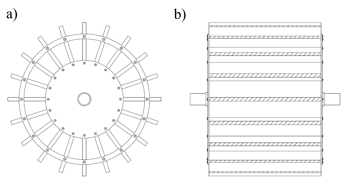
Hydro generators
Major property of hydro generators is relatively low rotation speed. Therefore there are more pair of poles (about several) to achieve 50/60 Hz of frequency. That provides also to increase rotors diameter and decrease rotor length. Moreover generator which works with reverse turbine (in generate mode and in engine mode), requires special construction to prevent machine against failure during many starts and stops in short time (several times in day cycle). At present capacity of a hydro-generator is above 400 MVA (San Chong in Korea 433 MVA) with rotation speed 360 rot/min. It gives 38MVA per pole. Such a high power generation is related with high temperature. Therefore hydro-generators have special cooling systems. It consists in air movement among each coil and each pole. That refinement provides to decrease machine size and increase value of first resonance velocity of centrifugal mechanic system. Coils are attached to the rotor by a clamp to prevent construction against electromagnetic damage. [10]
-
Description of technology|
Economic aspects|
Environment and public awareness|
Legislation|
Final comparison|
References