
MOTOR-DRIVEN SYSTEMS
SPEED CONTROL
One of the most important issues concerning motor-driven systems efficiency is its speed control. The lack of appropriate technologies has caused that the existing industrial sector is majorly inefficient and inflexible. Poland is one of the countries where the problem is significant. Many factories run their technology processes using dated regulation techniques or even without any regulation wasting a lot of energy. PEMPs estimates contend that the energy usage in motor driven systems can be conserved by 10-50% using modern control systems.
The most efficient way of changing the motors speed control can be obtained by variable-frequency drivers. Those devices were designed to change output motor speed by adjusting input AC frequency up to the pattern:
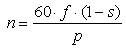
Where: n - output asynchronous motor speed
f adjustable AC frequency
s slip ratio depending of the load rate
p numbers of magnetic poles per phase
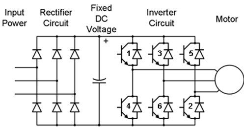
Variable-frequency drivers are basically built of rectifiers and inverters (Figure 17). The rectifier block is built of diodes which conduct electric current in only one direction. Thus the three phase input AC is converted into pulsating DC. The pulsation of output current can be smoothed by the low pass filter in more complex configurations. The inverter block is made of insulated gate bipolar transistors (IGBT) which are very durable, they can resist the power up to the hundreds of kilowatts. The flyback diodes connected in anti parallel with transistors are the protection against the voltage spikes which occur when the supply is abruptly removed.
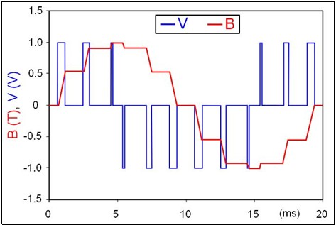
Conversion of DC to AC is obtained by synchronized cycles of switching the transistors. Each transistor is conductive for a set amount of time and the result of such effort is a round of pulse waves which create a quasi-sinusoid (Figure 18, blue). The width of the pulses and consequently the output frequency can be adjusted via microchip which properly manipulates the switching times of the transistors. That method is called pulse-width modulation (PWM) and it is currently the most commonly used controlling technique. The output pulses can be filtered and changed into ideal sinusoid, although in the case of electric motors it is not necessary. Figure W6 presents an example of PWM in an AC motor. As can be seen a sinusoid like voltage (blue) induces a magnetic field (red) which is in form of a curve which is very similar to the ideal sinusoid.
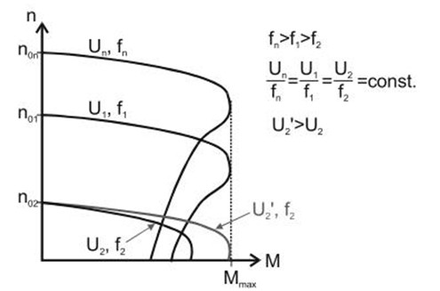
Very important issue in the motors speed adjustment is a control of the torque of the motor. Every modification of the motors speed results in a change of the motors torque. To keep the motors torque constant it is essential to change the feeding voltage value proportionately to the frequency (U/f=constant). For example if a motor is designed to operate at 400V and 50Hz, when the motor is slowed down by 50% to a frequency of 25Hz the voltage should decrease to 200V (Figure 19). An appropriate voltage value can be set with PWM.
Technique of changing the voltage proportionally to the frequency is called U/f control or scalar control. This is very simple method and devices using it are inexpensive. However also it has disadvantages. Since the speed of asynchronous motors depends on the load rate it is impossible or very difficult to set an exact speed. Prime method is to install a rotation sensor such as tachometer and adjust the frequency by trial and error. It is also possible to install a PI controller which will measure the speed and regulate the frequency by feedback, although this method provides long twilit states, also it is uneconomic and following on that not used in practice.
The rotors would not be able to rotate if there were no bearings connecting them to the stators. However even though the bearings severely simplify the movement of the rotor they are still a source of losses caused by friction. This is why the high efficient motors require high quality bearings which have to be optimally true to the electric motor.
Much better controlling system is provided by vector control. Basically it allows for precise control of the mechanical torque and magnetic flux in the motors by appropriate voltage adjustment. In comparison to scalar control this method is characterized with much more complex construction. It requires faster microchips and it is more expensive.
-
Definition of energy conservation and demand side management|
Technologies|
Financial funds|
Legislative and normative issues|
Data base
Copyrights © Arkadiusz Mysiakowski