
SMART GRID
ENERGY STORAGE
Energy storage system (ESS) is an essential element in the smart grid. Without a unit able to store a large scale energy within an electrical grid the existence of smart grid is limited. The importance of ESS is a result of growing input of renewable energy sources in power systems. Renewable energy sources (RES) such as wind turbines or photovoltaic cells are intermittent source of energy. Also they are wholly uncontrollable and unpredictable. Thus the only solution to control the energy flow generated by those sources is to use energy storage systems. Energy generated by RES instead of moving into the grid will be used to charge the energy storage systems. Then, when energy is needed (e.g. during the peak hours) power utilities will be able to power the electrical grid from the ESS. However the only existing forms of ESS are pumped storage hydroelectricities and compressed air storage systems which are very expensive and cover large areas. This is why scientists and engineers have been studying new technologies to find new energy storage systems which will fit in smart grid.
Most promising technologies are listed below.
Ultracapacitors They are similar to conventional capacitors, they have two conductors separated by a dielectric material. When there is a voltage put across the conductors, a static electric field is developed in the dielectric which stores energy. However the ultracapacitors have thousands times higher capacity which is achieved by using an active carbon in the dielectrics (Figure 11).
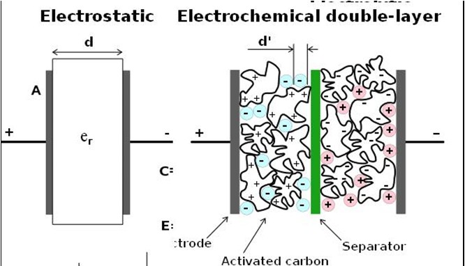
Even though ultracapacitors are characterized with high efficiency (95%), high rapidity of charging and discharging as well as long life span their ability to store the energy is much weaker than the other type energy storage systems. This is why the existence of ultracapacitors will be limited to the short-term storages in smart grid.
Flywheels Flywheels is a technology that stores the kinetic energy. It requires a rotor (known as flywheel) which is speeded by the generators when surplus energy is generated. When more energy is needed the rotor drives the generator consequently reducing its speed. Flywheels energy capacity is correlated with its mass and radius thus they are comparatively bigger than other kinds of energy storage systems. Also they require very solid and safe constructions because every accident with high speed rotating mass might be very dangerous. Flywheels do not suffer from memory effect and their life span is longer in comparison to batteries. However they are not able to store the energy for a long time due to the friction losses. This is why scientists and engineers study on superconducting magnetic bearings which will allow for flywheel to levitate in the magnetic field.
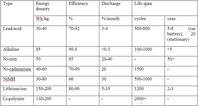
Batteries There are many kinds of batteries but the most promising technology is lithium-ion battery (LIB). It is very common technology, almost every laptop, cell phone and even electric vehicle is equipped with LIB. The batteries are built from two electrodes and electrolyte. The anode is made from carbon and the cathode from metal oxide, the electrolyte is a lithium salt in an organic solvent. That construction makes LIB the most promising technology for a long-term energy storage in smart grid. They have the highest energy density in comparison to other batteries, they do not suffer from memory effect and their self-discharge energy loss is comparatively low (Table 3). However, their life span is estimated to be 1200 cycles or 2-3 years which is not a satisfied value. Also, their components are made from rare minerals such as lithium.
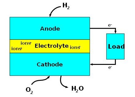
Fuel cells Fuel cells are devices which convert fuel energy into electricity. Their construction is similar to batteries, they have two electrodes and an electrolyte [Figure 12]. However they are not chargeable, they need fuel to work. Basically, the energy in fuel cells is generated by an oxidation phenomenon. Anodes of the fuel cells are usually fed by hydrogen and cathodes by oxygen. Hydrogen reacts with the anode and is consequently dissociated into proton ions H+ and electrons e-. Then, both ions and electrons travel to the cathode when they react with oxygen and create water. However, an electrolyte is conductive for protons only, it does not transmit oxygen ions nor electrons. This is why the electrons have to move to the cathode through the auxiliary branch feeding the loads. There are many kinds of fuel cells depending on the used materials and fuel. The most common ones are Proton-exchange membrane fuel cell (PEMFC), Reversible Fuel Cell (RFC),Direct-methanol fuel cell (DMFC),Solid-oxide fuel cell (SOFC), Molten-carbonate fuel cell (MCFC), Phosphoric-acid fuel cell (PAFC), Alkaline fuel cell (AFC). All kinds of fuel cells mentioned above differ with efficiency, price, qualified power and working temperature.
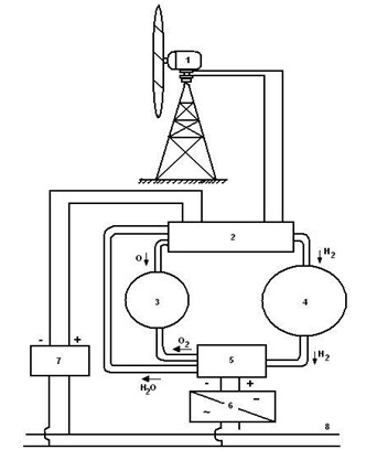
A simple example of fuel cell as an energy storage system can be seen on figure 12. A renewable energy source (1) generates the energy which is then used in the electrolyze tank (2) where the water is split into oxygen and hydrogen which are consequently stored in the tanks (3 and 4). Then when the energy is needed in the grid, the fuel cell (5) generates power using stored ingredients. The output power is in form of a DC thus it has to be converted to the AC by the inverter (6).
Superconducting magnetic energy storage (SMES) This technology in principle uses a magnetic field of a coil to store the energy. The energy stored in a coil is produced by a current flowing through the coil up to the pattern:
Where: E Energy stored in a coil [J]
I current flowing through the coil [A]
L inductance of a coil [H]
In normal conditions all the energy stored in the coil would be discharged by the resistance losses of the coil. However, a coil made of superconducting material when frozen below the critical temperature is characterized with no resistance at all. This is why in SMES the energy can steady persist in a form of a magnetic field.
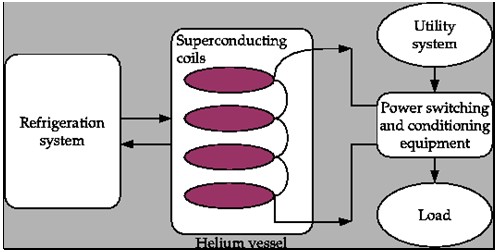
Figure 14 presents a basic operation of a SMES system. The transmission voltage is first stepped down in a transformer from kilo volts to several volts and then converted into DC in a rectifier. Then the power flows to the coil causing the DC to charge it. When the energy is needed in the grid, the coil acts like an energy source, it feeds the system with DC which is then converted to the AC in the inverter.
SMES are characterized with very high round-trip efficiency which is about 95%. However, it also consumes the energy. Estimates say that its efficiency falls 0.1% every hour due to the energy used for cooling. SMES system are chargeable rapidly and have long live span. They can be recharged within minutes indefinite times without any degradation of the coil. They also do not suffer from memory effect and do not produce any toxic oxides. However, the SMES is an expensive technology, mainly because of the use of superconducting materials.
There are several small SMES units operating as of yet. There are many 1MWh units used for power control, mainly to provide power quality at places where ultra-clean power is needed. There are also many bigger projects such as test model with capacity of 20MWh.
-
Definition of energy conservation and demand side management|
Technologies|
Financial funds|
Legislative and normative issues|
Data base
Copyrights © Arkadiusz Mysiakowski